This part describes the methodology in optimization and CFD evaluations. An total flowchart is proven in Fig. 5. The entire course of includes the optimization and the re-evaluation of the optimized design utilizing higher-fidelity simulations. The optimization and high-fidelity re-evaluation use DAFoam43 and OpenFOAM42, respectively. In what follows, we’ll describe every element of the methodology in subsections. To offer a self-contained however easy-to-follow paper for readers, we put extra particulars within the Supplementary Info and maintain the primary paper as concise as doable. We begin from CFD fashions concerned in each the optimization and re-evaluations after which observe up with different elements within the optimization framework.
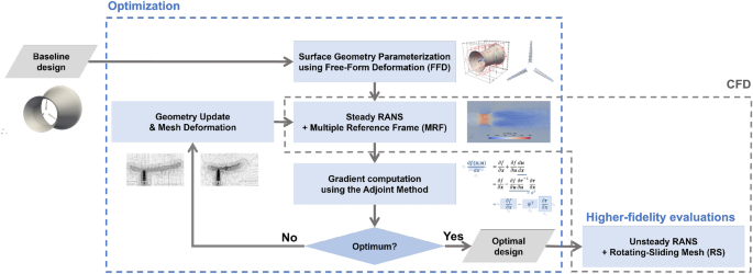
Diagram of the general course of, which incorporates optimization and re-evaluation of the optimum designs.
CFD fashions
The governing equations for the circulation discipline across the turbine (Fig. 1) are the Navier–Stokes equations
$$left{ {start{array}{*{20}l} {nabla cdot {varvec{ U}} = 0,} hfill {frac{{partial {varvec{ U}}}}{{partial t}} + nabla cdot ({varvec{UU}}) = – frac{1}{rho }nabla p + nabla cdot (nunabla {varvec{U}})} hfill finish{array} } proper.$$
(4)
the place (varvec{U}) is the circulation velocity and p is the strain.
We contemplate the Reynolds-averaged Navier–Stokes (RANS) equations with grids solely resolving the averaged elements of the circulation. One can apply the Reynolds decomposition (varvec{U} = overline{varvec{U}}+varvec{u}’) (and the identical for strain) to Eq. (4). (overline{varvec{U}}) denotes the averaged velocity in a time window or by an ensemble and (varvec{u}’) represents the zero-mean turbulent fluctuation. This results in the unsteady RANS equation:
$$start{aligned} {left{ start{array}{ll} nabla cdot overline{varvec{U}} = 0, frac{partial overline{varvec{U}}}{partial t}+nabla cdot (overline{varvec{U}},overline{varvec{U}}) = -frac{1}{rho }nabla {overline{p}} + nabla cdot (nu nabla overline{varvec{U}})- nabla cdot overline{varvec{u}’varvec{u}’}, finish{array}proper. } finish{aligned}$$
(5)
the place (overline{varvec{u}’varvec{u}’}) is the Reynolds stresses that should be approximated by turbulence fashions. On this work, the (k-omega) SST turbulence mannequin is used along with the automated near-wall therapy (see Supplementary Info A for particulars on each).
The rotating blades are dealt with in simulations by two blade-resolved approaches: the A number of Reference Frames (MRF) and the rotating-sliding mesh strategy (RS). The previous is used for regular RANS options (i.e., an answer with time-derivative phrases set to zero) with a number of totally different reference frames, whereas the latter is used instantly within the unsteady answer of Eq. (5). The MRF is utilized in optimization. The RS is outlined because the higher-fidelity strategy and used for optimized outcome re-evaluations (see Fig. 5). An in depth introduction of the 2 approaches is included within the following sections.
A number of reference frames (MRF) technique
The MRF technique is an environment friendly technique for modeling turbomachinery circulation. Within the MRF technique, the computational mesh stays stationary, and the rotational impact is dealt with via a rotational reference body. Particularly, the fluid area is separated into two areas: a rotational area surrounding the turbine blades with a blade-fixed reference body, and the remaining stationary area with an inertial reference body, as proven in Fig. 6. In each areas, the circulation is taken into account regular with respect to the corresponding reference body, so solely regular RANS equations should be solved.
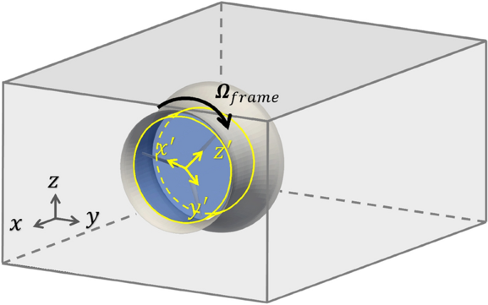
MRF technique illustration. The computational area is cut up into stationary and rotating (shaded blue) areas. The inertial and rotating reference frames are denoted by grey and yellow axes, respectively.
To be extra particular, within the rotational area, the blades are stationary and expertise a gentle influx. The circulation velocity within the blade-fixed reference body might be expressed by
$$start{aligned} varvec{U}_R=varvec{U}-varvec{Omega }instances varvec{r}, finish{aligned}$$
(6)
the place (varvec{U}) is the rate within the inertial reference body, (varvec{Omega }) is the rotation vector of the turbine blades, and (varvec{r}) is the space vector from the axis of rotation to the focus (place vector). The regular RANS equations within the rotational area should be established with the blade-fixed reference body, which requires additional formulations of each Eq. (5) and the (k-omega) SST mannequin equations. Though the implementation in OpenFOAM/DAFoam solves this entire set of equations, solely the rotational-region formulation relating to Eq. (4) is offered right here to offer the important thing insights of the strategy.
Combining Eq. (4) and Eq. (6), we receive (see Supplementary Info B for an in depth derivation)
$$start{aligned} {left{ start{array}{ll} nabla cdot varvec{U} = 0, frac{partial varvec{U}_R}{partial t} + nabla cdot (varvec{U}_Rvarvec{U}) = -frac{1}{rho }nabla p + nabla cdot (nu nabla varvec{U}) – varvec{Omega }instances varvec{U}. finish{array}proper. } finish{aligned}$$
(7)
The regular equations solved within the rotational area are Eq. (7), with (partial varvec{U}_R/partial t=0). Subsequently, within the MRF technique, regular variations of Eq. (4) and Eq. (7) are solved in stationary and rotating areas. Fixing these regular equations might be performed utilizing the SIMPLE algorithm44 applied as simpleFoam in OpenFOAM.
Though the RANS-MRF technique offers an environment friendly numerical answer for the turbine drawback (i.e., solely two regular RANS equations should be solved), its accuracy might be compromised due to two points. First, the rotational and stationary areas are often chosen in a subjective method. There isn’t any assure that the rotational area covers all of the circulation options ensuing from the rotating and discrete blades. Any mismatch between the selection of the area and the character of the circulation can result in errors on the interface and thus within the remaining outcomes. Secondly, for a lot of designs, the circulation might be unsteady in nature, particularly when circulation separation happens from the duct and/or blade surfaces. Assuming a gentle state answer, as within the RANS-MRF technique, can result in vital errors for such a unsteady circulation. Because of this, the RANS-MRF technique is taken into account a lower-fidelity mannequin within the context of this paper.
Rotating-sliding mesh strategy
The rotating-sliding mesh (RS) permits for the direct simulation of the unsteady RANS (URANS) equations (Eq. (5)) with mesh domains that exhibit relative movement. That is wanted for modeling rotating geometries. The underlying thought of this technique is to permit a area of the computational mesh to rotate with the turbine blades, as illustrated in Fig. 7. The rotating mesh additionally creates a technical drawback that the mesh on the rotating/non-rotating interface turns into non-conformal, i.e., the nodes at two sides of the interface don’t match up. The information switch throughout the interface, subsequently, must be dealt with by a particular interpolation technique involving a “supermesh”45, as described in Supplementary Info C.
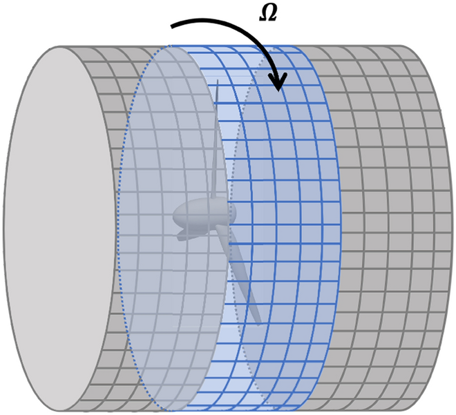
Rotating (blue) and stationary (grey) mesh, with non-conformal mesh interfaces.
Coupling URANS with the RS is, in precept, far more correct than the RANS-MRF technique because it captures the unsteady nature of the circulation. This may be important in simulating circulation round a ducted turbine as a result of the doable circulation separation from the duct floor might be captured higher. Nevertheless, within the URANS-RS, a small time step is required to resolve the blade rotation, so an extended simulation time is required for the answer to achieve a quasi-steady state. The computational value of the URANS-RS is therefore a lot greater than that of the RANS-MRF technique. On this paper, the URANS-RS is taken into account a higher-fidelity technique and is simply utilized in re-evaluating the efficiency of optimized designs.
Mesh configuration
The unstructured computational mesh is generated utilizing the OpenFOAM meshing instrument snappyHexMesh. A mesh overview is proven in Fig. 8. The scale of the computational area is (10.4Dtimes 10.4Dtimes 23.7L), the place (D=sqrt{(4/pi )A}=1.536) m is the utmost diameter of the duct, and (L=2.107) m is the size of the duct that’s taken from the baseline design. This area dimension is enough to keep away from a blockage impact upon checks. For the boundaries of the area, blended boundary boundary circumstances are utilized. To be extra particular, fastened velocity values and 0 strain gradient are imposed for flows coming contained in the area, whereas a zero velocity gradient and glued strain worth are imposed for flows popping out of the area. On the turbine blades and duct, no-slip boundary circumstances are utilized.
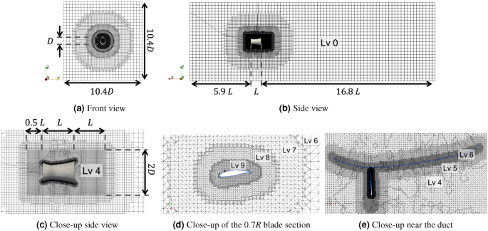
Mesh configuration for a ducted turbine, with (a) entrance view, (b) aspect view, (c) close-up aspect view to indicate the refinement area, (d) close-up view on the 0.7R blade part, and (e) close-up view close to the duct. The degrees of refinements are additionally proven within the figures.
To mannequin the circulation close to the turbine and instantly downstream with greater accuracy, a area of (2Dtimes 2Dtimes 2.5L) across the turbine is refined (see Fig. 8c). Throughout the refinement area, we apply three steps of grid refinement. First, a level-4 refinement is applied for the complete refinement area, i.e., every cell of the unique mesh is split into ((2)^4) cells. Then, additional refinements, as much as level-6 and level-9 towards respectively the duct and blade surfaces are utilized within the sub-regions near the surfaces. Lastly, prism layers are added near the surfaces, which comprise additional constantly refined cells towards the surfaces (2 and three layers are used for the previous and latter, each with the growth ratio of 1.1). The prism layer offers higher decision for boundary layers and is important for acquiring well-convergent ends in the grid sensitivity research proven later within the Outcomes and Dialogue part.
On this work, three grid resolutions, M0, M1, and M2, are used with an growing variety of cells, i.e., additional refinement from M0 to M2. The coarsest grid M0 is used within the RANS-MRF within the optimization course of and has 2-3 million cells (the precise quantity depends upon turbine geometry and re-mesh process in optimization, nevertheless it roughly incorporates 1.5 million cells within the refinement area and an identical variety of cells within the remaining area). In M1 and M2, the complete mesh area (together with background mesh and refinement area) is uniformly refined in every course by the elements of about 1.3 and 1.6, respectively, resulting in 4-5 million cells for M1 and 7-8 million cells for M2. All grids M0, M1, and M2 are used within the URANS-RS re-evaluation, together with the grid sensitivity research.
Optimization
Sequential Quadratic Programming (SQP)46, applied in SNOPT47, is used to unravel the optimization drawback. One of many difficult duties is to acquire the gradient of the target perform (nabla C_P) with respect to all design variables. The next subsections talk about the elements (see Fig. 5) concerned within the gradient computation: (1) geometry parametrization and mesh deformation; (2) adjoint technique. The gradient data is then used within the SQP algorithm to acquire the subsequent design factors. The process iterates till satisfying convergence standards or additional design enhancements usually are not achievable.
Geometry parametrization through FFD technique
It’s essential to parametrize the geometry to deform the floor mesh. On this work, the Free-Kind Deformation (FFD) technique48 is used for the geometry parametrization, applied within the bundle pyGeo49,50. The precept of the FFD technique is to surround the floor mesh nodes in an FFD field with a specified variety of management factors (also called FFD factors). The FFD factors are analytically linked to the enclosed floor nodes utilizing tri-variate B-splines. Extra particulars are offered in Supplementary Info D. Controlling the FFD factors allows clean deformation of the enclosed geometry. Fig. 9 exhibits two examples of geometry deformation managed by the FFD technique in two and three dimensions.
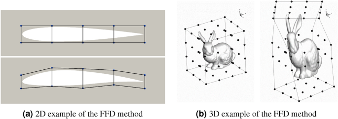
Examples of geometry deformations with FFD factors. (a) A 2D NACA0012 airfoil (from the DAFoam tutorial) and (b) a 3D Stanford bunny (determine taken from Kenway et al.49).
Determine 10 exhibits an summary of the FFD setup for our ducted turbine. Two ranges of FFD containers are used, with one mother or father field (black) enclosing all duct and blade geometries and two youngsters containers (pink and blue) enclosing the duct and blades. The 21 design variables within the optimization drawback can now be represented by 21 levels of freedom (DoF) related to the FFD factors. The kid FFD field for a person blade has 32 FFD factors positioned on 8 sections. Twist variables rotate the 4 FFD factors in regards to the reference axis situated on the quarter chord line. Scale variables scale the cross-section by shifting the 4 management factors to increase or contract concurrently. The FFD factors throughout totally different blades are linked to make sure the identical deformation for all blades.
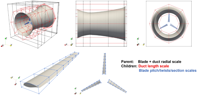
Geometry parametrization of a ducted turbine via the FFD technique. Prime: totally different views of the general FFD setup, the place the parental FFD field (black) controls the radial scales of each duct and blades, the kid duct FFD field (pink) controls the size of the duct, and the kid blade (blue) FFD field controls the pitch/twist angles and sectional areas of the blades. Backside: Nearer views of the FFD setup for the blades.
The kid FFD field for the duct incorporates 112 FFD factors positioned on seven sections, however total just one variable is outlined to regulate all FFD factors to vary the duct size l. When altering the duct size, all duct FFD factors transfer within the axial course with perturbations proportional to their distances from the throat. This motion is to make sure that the throat is constantly situated at 26.4% of the general duct size. Observe that seven sections usually are not essential. This alternative is principally for comfort throughout setup.
The mother or father FFD field handles the constraint (3f) on the tip-gap ratio and the situation (D_text {exit}=sqrt{(4/pi )A}=1.536) m. Twenty-eight FFD factors are positioned on seven sections within the mother or father field, wherein the FFD factors for the final three sections are carefully packed horizontally and stay stationary all through the optimization, such that (D_text {exit}=sqrt{(4/pi )A}) is assured. The 16 FFD factors on the primary 4 sections from the duct inlet are used to regulate the duct diameters, i.e., design variables (d_i). As these FFD factors transfer radially, the kid FFD containers (enclosed within the mother or father FFD field) deform and transfer the embedded floor geometry accordingly. Subsequently, the constraint (3f) is routinely happy because the blade expands/contracts proportionally to the duct throat. This implementation of the complicated FFD setup for ducted generators, we consider, is a novel utility.
Adjoint technique for spinoff computation
To compute the spinoff of an goal perform (on this case, the facility coefficient (C_P)) with respect to design variables, the adjoint technique46 is used. So as to clearly clarify the adjoint technique, notations are launched first as follows: Let (varvec{x}equiv { { theta _i, b_i }_{i=1}^{8}, {d_j}_{j=1}^{4}, l} in {mathbb {R}}^{N_x}) with (N_x=21) because the design variables. Let (varvec{s}in {mathbb {R}}^{M}) be the state variables within the answer of the RANS-MRF equation. Right here (M sim {mathscr{O}}(10^7)) consists of three velocities and strain at every cell within the computational grid. Our purpose is to compute (dC_P/dvarvec{x} in {mathbb {R}}^{21}). If a finite-difference technique is used to compute the spinoff, one wants no less than 22 CFD simulations for spinoff computation, even with the lowest-order approximation. That is computationally prohibitive for our utility.
For the adjoint technique to compute (dC_P/dvarvec{x}), step one is to jot down the perform (C_P(varvec{x},varvec{s}(varvec{x}))), and specific its complete spinoff with respect to (varvec{x}) as
$$start{aligned} underbrace{frac{dC_P}{dvarvec{x}}}_{1times N_x}=underbrace{frac{partial {C_P}}{partial varvec{x}}}_{1times N_x}+underbrace{frac{partial {C_P}}{partial varvec{s}}}_{1times M}underbrace{frac{dvarvec{s}}{dvarvec{x}}}_{M instances N_x}, finish{aligned}$$
(8)
the place (partial C_P/partial varvec{x}) needs to be thought of because the change of energy coefficient (C_P) because the design variables (i.e., geometry) are different, with circulation answer (varvec{s}) remaining unchanged. (partial C_P/partial varvec{s}) is the change of (C_P) because the circulation answer (varvec{s}) adjustments with a set turbine geometry. These partial derivatives are comparatively straightforward to compute, with extra particulars offered in Supplementary Info E.
The time period that’s tough to compute in Eq. (8) is (dvarvec{s}/dvarvec{x}). To compute it, one must additional contain the RANS-MRF state equations when it comes to their discretized residual kind (varvec{R}(varvec{x},varvec{s}(varvec{x}))=0). Right here (varvec{R}(varvec{x},varvec{s}(varvec{x})) in {mathbb {R}}^M) contemplating the identical variety of equations because the variety of unknowns in (varvec{s}). Since (varvec{R}(varvec{x},varvec{s}(varvec{x}))) ought to stay zero with a change of (varvec{x}) (if the circulation answer is appropriately obtained), we’ve got
$$start{aligned} underbrace{frac{dvarvec{R}}{dvarvec{x}}}_{Mtimes N_x}=0Rightarrow underbrace{frac{partial varvec{R}}{partial varvec{s}}}_{Mtimes M}underbrace{frac{dvarvec{s}}{dvarvec{x}}}_{Mtimes N_x}=-underbrace{frac{partial varvec{R}}{partial varvec{x}}}_{Mtimes N_x}. finish{aligned}$$
(9)
Direct answer of Eq. (9) provides
$$start{aligned} frac{dvarvec{s}}{dvarvec{x}} = -underbrace{left[ {frac{partial varvec{R}}{partial varvec{s}}}right] ^{-1}}_{Mtimes M}underbrace{frac{partial varvec{R}}{partial varvec{x}}}_{Mtimes N_x}. finish{aligned}$$
(10)
It’s worthwhile to debate the computational value related to Eq. (10) at this level. The matrix multiplication in Eq. (10) results in a computational complexity of ({mathscr{O}}(M^2 N_x)) that could be very costly since (Msim {mathscr{O}}(10^7)) and (N_x) can be giant. This must be added by the price to invert a (Mtimes M) matrix, which is, normally, costlier. Even when one makes use of some iterative solver for linear techniques to unravel Eq. (9), the process must be repeated for (N_x) instances since (dvarvec{s}/dvarvec{x}) (in addition to the RHS) has (N_x) columns. The computation is, subsequently, additionally very costly.
Then again, the computational value might be considerably diminished by merely substituting Eq. (10) to Eq. (8) and contemplating a re-grouping of the multiplications:
$$start{aligned} underbrace{frac{dC_P}{dvarvec{x}}}_{1 instances N_x}=underbrace{frac{partial {C_P}}{partial varvec{x}}}_{1 instances N_x}-left( underbrace{frac{partial {C_P}}{partial varvec{s}}}_{1 instances M}underbrace{left[ {frac{partial varvec{R}}{partial varvec{s}}}right] ^{-1}}_{M instances M}proper) underbrace{frac{partial varvec{R}}{partial varvec{x}}}_{M instances N_x}. finish{aligned}$$
(11)
As an alternative of computing Eq. (10), the multiplication grouped within the parenthesis in Eq. (11) is computed first. This computation might be performed by fixing the so-called adjoint equation (the adjoint is equal to the transpose of an actual matrix in our case)
$$start{aligned} underbrace{left[ {frac{partial varvec{R}}{partial varvec{s}}}right] ^{T}}_{Mtimes M}underbrace{varvec{psi }}_{Mtimes 1}=underbrace{left[ frac{partial {C_P}}{partial varvec{s}}right] ^{T}}_{Mtimes 1} finish{aligned}$$
(12)
whose answer transpose offers
$$start{aligned} varvec{psi }^{T}=frac{partial {C_P}}{partial varvec{s}}left[ {frac{partial varvec{R}}{partial varvec{s}}}right] ^{-1} finish{aligned}$$
(13)
because the parenthesis time period in Eq. (11).
The answer of Eq. (12) includes fixing a linear system solely as soon as, as a substitute of (N_x) instances as wanted for Eq. (9), and therefore is far cheaper (additionally in comparison with the direct computation of Eq. (10)). The computational value to unravel Eq. (12) is usually just like the RANS-MRF computation. Subsequently, in every iteration of the optimization, the computational value is in the identical order as one RANS-MRF answer. The one remaining element is the calculation of partial derivatives (partial varvec{R}/partial varvec{s}) in Eq. (12), which might be present in Supplementary Info E with different derivatives talked about above.
Quantity mesh deformation
When marching to the subsequent design level, the turbine geometry is deformed. The whole computational quantity mesh is deformed accordingly.
The amount mesh deformation is computed based mostly on the analytic inverse-distance weighting technique51, applied within the IDWarp bundle52. Given a 2D floor, for instance, a blade floor, with N floor mesh nodes, the geometry deformation results in the motion of every node. Two portions ((M_i, b_i)) are assigned for every node with (i=1,2,…,N), the place (b_i) is the interpretation distance of the node and (M_i) is the rotation matrix such that (n_i^{new}=M_i n_i^{previous}) with (n_i^{new}) and (n_i^{previous}) the conventional vectors on the node. Particularly, each (n_i)’s are computed by a weighted common of the conventional vectors for all surrounding cell faces of the node. After ((M_i, b_i)) are obtained for (i=1,2,…,N), the deformation of any quantity mesh might be computed by summing the contribution from every floor node, i.e., (Delta varvec{r}=sum _{i=1}^N w_i (M_i varvec{r} + b_i – varvec{r})) with (varvec{r}) being the coordinates of a quantity node and (Delta varvec{r}) its motion. The weighting issue (w_i) has the empirical kind51,52 that grows in a polynomial kind with the inverse of the space between the quantity and floor nodes. Determine 11 exhibits the deformation of the computational mesh throughout a ducted turbine optimization for example.

Computational mesh deformation in the course of the geometry deformation of a ducted turbine.


