The outflow over an ogee-crested spillway is specified by24:
$$start{aligned} Q=C , L , H^{3/2} finish{aligned}$$
(1)
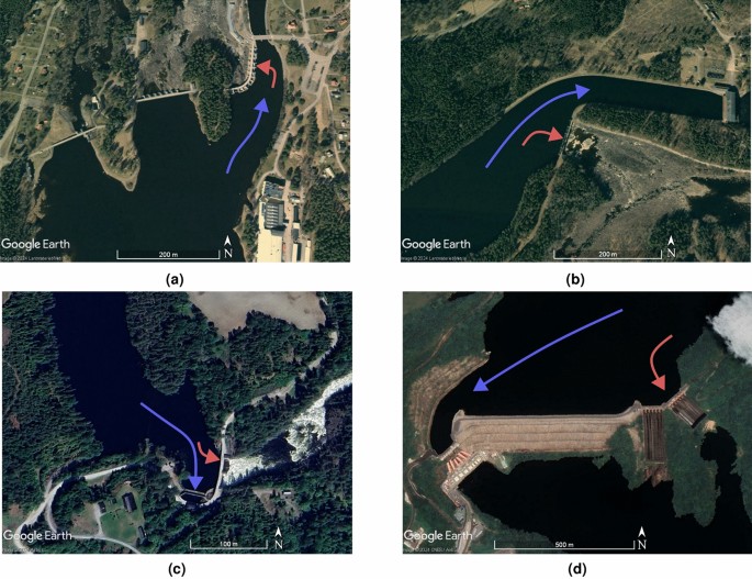
where Q denotes the discharge, C represents the spillway’s discharge coefficient, L indicates the spillway dimensions and H is the total head above the spillway crest. To correct for contraction losses that occur at the corner of the abutment and the spillway inlet, the common design approach involves utilizing a reduced effective spillway size, calculated as: (L_{textual content {eff}}=L-(n, K, H)), where L is the unadjusted size, n is the number of corners, and K is a contraction loss coefficient. A frequently referenced contraction coefficient is found in the handbook of Creager and Justin25, specifically (K=0.1). This effect is depicted in Fig.2a, where the complete length of the spillway is not utilized due to the sharp corner, resulting in a contraction loss. These losses diminish the effective discharge capacity, especially when multiple corners or obstructions exacerbate the situation. The existence of indirect approach flow further compounds these losses, leading to localized reductions in efficiency.
(a) Plan view of straightforward streamlines for a spillway with indirect approach, showing contraction occurring around the abutment corner. (b) Section view of a spillway, defining weir height and overflow height.
Chow26 additionally provides summaries of the studies by USGS and USACE on topics such as pier design and nose shapes. Further references include Yarnell27, which compares and elaborates on key references from the turn of the previous century concerning piers and channel constrictions, including works by Rehbock, D’Aubuisson, and Weisbach. While the primary focus is on bridge pier and channel obstructions, the effects of pier geometry and flow angle are briefly reviewed. This led to the publications by USACE28, which feature K-values that depend on the shape and location of the pier, as defined below.
$$start{aligned} L_{textual content {eff}}=L-2,(n , K_p + K_a) , H finish{aligned}$$
(2)
where (K_p) and (K_a) are contraction coefficients signifying the piers or abutments respectively, with a maximum value of 0.2 found for (K_a).
There is a distinction in the application of total head (H) and overflow height (h), with the latter reflecting the height over the spillway crest without including the velocity head component. The relationship between overflow height (h) and weir height (P), as illustrated in Fig. 2b, is a vital factor for comprehending contraction losses and spillway discharge efficiency. The discharge coefficient (C) is affected by overflow height, which dictates the recommended curvature of the spillway chute. A higher overflow to weir height ratio (h/P) suggests increased approach velocities, leading to larger contraction losses. These findings are particularly significant for run-of-river structures, which often operate at lower relative weir heights. This investigation incorporates these adjustments into its analysis to better understand the combined effect of indirect approach flow and geometric alterations on spillway discharge capability. By comparing experimental results with theoretical predictions derived using contraction loss coefficients, this research emphasizes the limitations of existing design equations and the need for revisions in design practices for contemporary hydraulic infrastructure.
Model setup
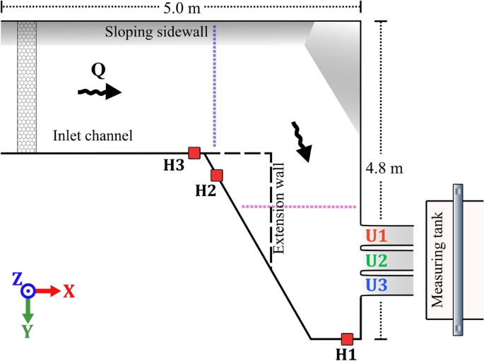
Experiments were conducted at Vattenfall’s hydraulic laboratory in Älvkarleby, Sweden. A schematic overview of the model is presented in Fig. 3. At the inlet, the model is supplied by two pumps with a total capacity of 300 liters per second. Inlet pipes are connected to the model, discharging into a smaller inlet basin before entering the channel. Both inlet pipes are fitted with electromagnetic flow meters for discharge measurement. To ensure an even flow distribution, several plates of perforated metal are placed near the pipe exits to balance out the flow entering the inlet basin. Finally, a honeycomb mesh leads into the main channel, serving as the ultimate flow-regulating structure and creating a more uniform turbulence pattern, as these flow characteristics can be utilized as boundary conditions for CFD. The channel is constructed from metal plating with dimensions of approximately 5 x 5 m. From the inlet channel, a sharp corner in the model directs the flow obliquely towards the three spillway outlets. The elevated floor consisted of metal plates welded onto a metal frame, allowing water to fill the void beneath the raised floor. Small openings in the floor permitted water to seep up from below. Measures have been taken to seal the edges and floor near the outlets. The geometry of the spillway outlets was sourced from the hydropower facility at Torpshammar, Sweden, with the shape scaled at 1:50 and crafted out of polyurethane. Manufacturing imperfections caused slight variations among the three outlets; however, the maximum variation was found to be less than 3 mm, within 0.1(%) of the intended width of 300 mm. To monitor the water level in the channel, water is rerouted through tubing into separate magnetostrictive sensors (see Fig. 3 for positions of the sensors).
The flow measurement for a specific spillway outlet was accomplished by channeling the flow from the spillway chute into a tank of 6 m(^3) suspended on 4 load cells. Internal testing of the load cells at Vattenfall’s concrete laboratory confirmed an uncertainty of ± 0.1%. Sensor drift was accounted for in post-processing by calibrating the measurements after blocking two of the three outlets. The load cell data, combined with readings from the magnetostrictive sensors and volumetric flow rate from the pumps, were recorded using Labview software from National Instruments. As the recording captures data before and after water is diverted into the measuring tank, an interval of at least 30 seconds of flow was taken for data analysis; when feasible, additional time was utilized. This limitation arises from the volume constraint of the weighing tank, as larger discharges filled the tank at an accelerated rate. The average measurement time across all experiments was 70 seconds. Comparisons between short and long time-series demonstrated differences within the 1% uncertainty of the measurement devices.

Topographical representation of the experimental arrangement with ADV locations indicated by purple and blue dotted lines on the spillway and within the channel. Honeycomb flow rectifier established at the upstream end of the channel. Openings for the magnetostrictive sensors represented with red squares.
The output from the load cell is graphed over time, yielding a gradient that provides an accurate measurement of outflow through the respective spillway outlet. This process is repeated for all three spillway exits with a constant inflow to the model. The aggregation of quantified discharge through the spillway outlet can be compared to the incoming flow recorded from the pumps, generating a percentage of the total flow that has traversed through each individual outlet. Calibration involved blocking two outlets and modifying the signal from the load tank to align with the inlet flow. Data were collected for each individual outlet, followed by three iterations for that particular inflow, repeated over three days, totaling nine sets of data for each inflow. During measurements, there was minor leakage between the outlet and weighing tank, estimated to be below 0.1 l/s.
The initial design, referred to as the original configuration, featured rounded edges with a 40 mm radius on the abutments, and a 38 mm radius for the piers, as illustrated in Fig. 4a. To investigate the effects of corner geometry alterations, flat aluminum plates with a thickness of 1.5 mm were affixed to the spillway piers and abutments, introducing sharp corners at the spillway inlets, as demonstrated in Fig. 4b. The model was further modified by adjusting the channel geometry to include an extension wall, enhancing the degree of lateral inflow. The extension wall is marked with a dashed line in Fig. 3. Model configurations featuring this addition have been designated as with extension wall, while those without have been labeled without extension wall.
By merging Eqs. (1) and (2), an estimate of the anticipated increase in water level required to discharge the same quantity of water can be computed. In this instance, L in the equation would be adjusted by -9 mm, corresponding to the change in total width, while H would denote the corresponding H for (Q=90) l/s.
$$start{aligned} left( frac{Q}{C,(L-2(n , K_p+K_a), H)}proper) ^{2/3}=H_{new} finish{aligned}$$
(3)
Utilizing two distinct values for L, one set at 900 mm, the initial width, and the second value at 891 mm, reflecting the reduced width by (-9) mm. Implementing Eq. (3) results in a difference in (H_{new}) of 1.1 mm, suggesting that any variations in water level exceeding 1.1 mm are not attributable to the decreased width of the spillway. It is crucial to note that for the calculation of the discharge coefficient, the actual dimension is employed, thus the reduction caused by the corner profiles is included in the comparison depicted in Fig. 6.

(a) Initial configuration of the outlet with rounded piers displayed without water. (b) Outlet exhibiting corner profile configuration shown for a low flow scenario.
To capture the flow field at relevant positions within the channel, Acoustic Doppler Velocimetry (ADV) was selected as a tool. ADV has been extensively utilized in scholarly work, with instances such as Jeon et al.29 and Pandey et al.30, where ADV was employed in smaller channels to document flow velocities around submerged obstacles. The specific ADV device utilized in this investigation was the Nortek 10 MHz Velocimeter. Data were recorded over a duration of one minute with a sampling frequency of 100 Hz. The timing of the ADV recordings was selected as a compromise based on the data required to achieve reliable average values and was considered sufficient to produce viable flow velocity readings, balanced against the number of data points that needed to be collected. In existing literature, the duration used for ADV recording varies; Jeon et al.29 employed 5 minutes, Pandey et al.30 used 3 minutes, while Singh et al.31 utilized 4 minutes. Other recent studies used as little as 30 seconds of recordings for gathering average velocities at a frequency of 50 Hz, as in Son et al.32, whereas Kumar et al.33 achieved the same frequency with 1-minute recordings. The gathered ADV data was post-processed in MATLAB according to guidelines from the manufacturer for average velocities, filtering the data based on a signal-to-noise ratio (SNR) of 5 and correlation of 70. Since the ADV probe must be inserted into the flow, it is considered an intrusive method. However, the system does not require laser and typically does not require artificial seeding. Adequate particulate matter was suspended within the water, negating the need for artificial seeding to acquire quality data. Limitations were observed near the sloped side wall, where the proximity to the bed restricts measurement as reflections from the slanted wall caused significant interference resulting in poor-quality data. Similarly, data gathered near the inlet was analyzed but deemed unusable due to high variability in velocities and closeness to the inlet and bottom, which contributed to the low quality. ADV measurements were taken at two sections across the channel. Along these two lines, a grid of points was recorded at intervals of 10 cm in the direction perpendicular to the wall associated with the spillway, and 5 cm intervals in the z-direction. The number of grid points collected depended on the water level as increased flow allowed for an additional point to be measured. The first measurement site was located directly after the corner leading towards the outlets, as indicated by a blue line in Fig. 3. The second site, marked by the red line in Fig. 3, was positioned at a distance of 30 cm upstream of the spillway.

