
Quaranta et al. 14 suggested a collection of formulas to approximate the weight of hydropower tools. The formulas, with a typical outright mistake which is usually listed below 20%, verified to be ideal for massive initial quotes. These formulas were right here put on the EU hydropower data source (currently explained in 15 and consisting of wind turbine kind, head ( H, m), circulation price ( Q, m 3/ s), power ( P, MW) and variety of devices per plant), to approximate the weight of the electro-mechanical tools, thinking a certain weight of 78 kN/m 3 The collective mounted capability consisted of in this data source is 154 GW (158 GW consisting of UK), which decreases to 151.6 GW when thinking about the nuclear power plant whose all the previously mentioned information are understood. In this job, the evaluation was put on the 151.6 GW of nuclear power plant with recognized information standing for practically the entire European Union’s hydropower fleet in regards to mounted capability. Outcomes were linearly theorized to the existing mounted capability of 154 GW of the EU. The geographical circulation of the European hydropower fleet is shown in Fig. 2.
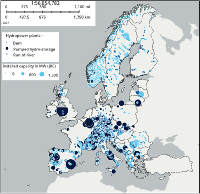
Circulation of hydropower plants in the entire Europe according to the JRC hydropower data source, consisting of 190 GW, readily available openly at the European Compensation’s web site https://energy-industry-geolab.jrc.ec.europa.eu/.
Kaplan, Prop and Francis joggers
The weight G (kN) of steel joggers is a feature of the wind turbine size D (m):
$$ G = {6} D ^ {{{2}. {75}}}; {message {for Francis}} $$
( 1 ).
$$ G = {2}. {3} D ^ {{3}}; {message {for Prop}} $$
( 2 ).
$$ G = {3} 0D ^ {{{1}. {9} 0}}; {message {for Kaplan}} $$
( 3 ).
where the size D (m) can be computed as suggested in 16 as a feature of the rotational rate N (rpm). The rotational rate can be approximated as a feature of the dimensionless circulation price Q *(= frac {{Q} _ {nom}} {sqrt {2gH} {H} ^ {2}} ) (Eq. 4), as outlined in 17 Under the classification of Francis wind turbines we likewise consisted of Pump-as-Turbines, Deriaz and Girard wind turbines.
$$ N= left( alpha {Q} ^ {* beta} {right) frac {|) frac {} sqrt {2gH}} {H} $$
( 4 ).
where α= 20.3 and 26.8 for Francis and Kaplan-Bulb wind turbines, specifically. β= − 0.36 and − 0.38 for Francis and Kaplan-Bulb wind turbines, specifically. When using Eq. (4 ), the very same coefficients made use of for Kaplan wind turbines were likewise made use of for Light bulb wind turbines, when the certain rate, shared as N ( sqrt {P} {H} ^ {-1.25} ), was over 700. The certain weight was readied to 78 kN/m 3
Pelton joggers
The weight of Pelton joggers can be approximated by Eq. ( 5 )
$$ Gleft( {{message {kN}}} {right) = {|) = {} 439} 0; f _ {1} ^ {2.5}; {message {with R}} ^ {{2}} = 0. {95} $$
( 5 ).
with f 1=( sqrt {frac {Q/ {n} _ {j}} {sqrt {2 g H}}} ), where Q is the circulation each (m 3/ s), n j is the variety of jets and H is the internet head (m). The criterion f 1 is an indication of the jet size, and therefore of the jogger size and size. The typical mistake of Eq. (5 ), approximated in 14, was 19.8%.
Banki joggers
The adhering to formulas were made use of:
$$ G = {24}. {7}; Q ^ {{0. {85}}}, {message {for the mechanical}}/ {message {hydraulic team}} $$
( 6 ).
$$ G =, 0. {11};P _ {el} ^ {{0. {98}}}, {message {for the generator}} $$
( 7 ).
where P el is the electric power in in kW and Q is the style circulation in m 3/ s. The weight computed by Eq. ( 6) consists of the jogger, the outside covering, the inlet nozzle and sustains, according to information of IREM MEDICAL SPA (Italy). In this research, we thought that fifty percent of the weight is of the remainder and the jogger is taken into consideration as “casing”.
Electric generator
The weight relies on the generator rotational regularity N (rpm) and power P (MVA) according to Eq. (8 ).
$$ G = {alpha} {{left( frac {|( frac {} P} {sqrt {N}} {right)} |)}} ^ {beta} $$
( 8 ).
The typical outright mistake approximated in 14 was 7.4%. For Banki wind turbines, Eq. ( 7) was made use of to approximate the generator weight. The worths of the coefficients α and β are noted in Table 1.
Housing
The covering, generally made from steel, is a fixed element that confines the turning jogger and the vanes. Its form is instead straightforward for Pelton wind turbines, while it is spiral for response wind turbines (e.g., Kaplan and Francis wind turbines).
For Pelton wind turbines, the casing weight can be approximated by the adhering to formulas:
$$ G = {1177} f + {4}. {message {92 for upright axis}} < < {1} 0 {message {MW}} $$
( 9 ).
$$ G = {763} f + {2}. {24}; {message {for straight axis}} < < {1} 0; {message {MW}} $$
( 10 ).
$$ G = {134}. {8} f + {message {99 for upright axis}} > > {1} 0; {message {MW}} $$
( 11 ).
with f= D 2 ( sqrt {frac {Q/ {n} _ {j}} {sqrt {2 g H}}} ), D is the jogger size (m), Q is the circulation each (m 3/ s), n j is the variety of jets and H is the internet head (m). R 2 varies in between 0.71 and 0.94 relying on the arrangement, and the typical outright mistake was approximated to be listed below 30% 14 When the number of jets was greater than 2, the upright axis arrangement was selected. The variety of jets can be approximated as:
$$ {n} _ {j} = frac {Q} {0.0039 {P} ^ {0.5643}} $$
( 12 ).
where P (kW) and Q (m 3/ s) are the worths each. For more information see 18
For response wind turbines, Brekke 19 revealed that the weight G of high head big Francis spiral covering has actually practically gotten to a secure worth with the years of 30 kN/MW of mounted capability, and no more weight decrease is anticipated. For smaller sized wind turbines, the adhering to formulas were made use of 14:
$$ frac {G} {P} =2.84 {{left( frac {|( frac {} Q} {sqrt {H}} {right)} |)}} ^ {-0.81} message {for Upright axis wind turbines} $$
( 13 ).
$$ frac {G} {P} =frac {1032} {H} message {for Straight axis wind turbines} $$
( 14 ).
where P is the mounted power capability shared in MW and the G is the weight in kN, Q is the circulation in m 3/ s and H the internet head in m. R 2= 0.8 and typical outright mistake was approximated to be 20%. In our evaluation, we used these formulas to nuclear power plant listed below 10 MW, and thought 30 kN/MW for bigger nuclear power plant. According to information of Zeco Hydropower, upright axis wind turbines are made use of listed below 1.25 m 3/ s (from an easy fact, without specific technological validation).
The weight of overview vanes was computed thinking about the typical design technique, as G= z ∙( l ∙ s) ∙ m ∙ h ∙ ρg, where l is the vane size, s is the vane density (20% l), m= 0.5 is the filling up proportion of the sample (the actual sample– NACA account– is etched in the rectangle-shaped location l ∙ s), h is the vane elevation and z is the variety of vanes. The variety of vanes can be computed as 0.25 D 0.5+ 5 20 with D the size in mm, l is computed to make certain that when all the vanes are shut, the representative size is totally shut (and vanes ought to overlap by 15%), h=( 0.134 ln( N s) − 0.45) D with the size D in m 16
Draft tube
The adhering to empirical formulas were made use of to approximate the weight of the draft tube for wind turbines listed below 10 MW:
$$ frac {G} {{N} _ {s}} =0.305, {D} ^ {3} quad message {for Straight axis Francis wind turbines with joint draft tube} $$
( 15 ).
$$ frac {G} {{D} ^ {3}} =16.2, {D} ^ {-1.85} quad message {for Upright axis Kaplan wind turbines with joint draft tube} $$
( 16 ).
$$ frac {G} {{N} _ {s}} =0.0205, {D} ^ {1.95} quad message {for Prop wind turbines} $$
( 17 ).
The joint draft tube, which is one of the most made use of and effective kind, was thought for Francis and Kaplan wind turbines, while Prop wind turbines make use of straight draft tubes 14 R 2 > 0.82 and the approximated typical outright mistake was 20%. N s is the certain rate shared as N ( sqrt {P} {H} ^ {-1.25} ), with P in kW, the internet head H in m and N in rpm. D is the draft tube inlet size in m, computed by formulas suggested in 16 For Kaplan wind turbine devices with joint and S-type draft tube, the weight approximated by Eq. (16 ) just consists of the initial component of the draft tube, due to the fact that the 2nd (diffuser) component is usually made from concrete constructed on-site. These formulas are taken into consideration legitimate likewise for nuclear power plant over 10 MW.
Steel in the giant framework
The steel made use of in the giant can be approximated according to 21, in KN, as:
$$ G= k (n+ R) {C} ^ {0.358} {D} ^ {1.074} $$
( 18 ).
where k= 32.5 and 79.6 for response and impulse wind turbines, specifically. C= Crane capability in lots, D= Jogger throat size in meters, n= Variety of devices in giant, R= Fixing bay proportion, that can be thought as equivalent to 0.5 14 The Crane capability can be approximated as G= 46 ( {{left( frac {|( frac {} P} {sqrt {N}} {right)} |)}} ^ {0.8} ) 22, likewise to Eq. ( 8 ). This worth does not come from the electro-mechanical tools.