Numerical Configuration
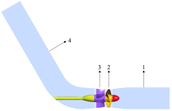
The axial-flow pump is comprised of an inlet pipe, impeller, guide vane, and outlet pipe. Figure 1 illustrates the 4 moving sections model of the pump. Table 1 presents the primary characteristic data of the pump. This paper primarily investigates the effects of different cascade density on the efficiency of the pump, with the analysis results serving as a reference for the optimization of axial-flow pump impellers.
3D model of axial-flow pump. (1) Inlet pipe; (2) Impeller; (3) Guide vane; (4) Outlet pipe with a 60° angle.
Governing Equations and Turbulence Model
The fluid medium within the axial-flow pump is a continuous incompressible liquid, and the flow of water is driven by the rotation of the impeller. Given that the temperature of the fluid remains constant, the energy equation can be disregarded. Consequently, the continuity equation ultimately resolved by CFD is represented in the following formulation: (1) The momentum equation is detailed in Equation (2) below.
The continuity equation is:
$$frac{{partial rho}}{{partial t}} + frac{{partial}}{{partial x_{j}}}( rho u_{j} ) = 0$$
(1)
The momentum conservation equation is:
$$frac{{partial (rho u_{i})}}{{partial t}} + frac{{partial}}{{partial x_{j}}}(rho u_{i} u_{j}) – frac{{partial}}{{partial x_{j}}}left[mu left(frac{{partial u_{i}}}{{partial x_{j}}} + frac{{partial u_{j}}}{{partial x_{i}}}right)right] = -frac{{partial p}}{{partial x_{i}}} – frac{{partial}}{{partial x_{j}}}left(rho overline{{u_{i}^{{prime}} u_{j}^{{prime}}}}right) + S_{M}$$
(2)
Where:
$$- rho overline{{u_{i}^{{prime}} u_{j}^{{prime}}}} = mu_{t}left(frac{{partial u_{i}}}{{partial x_{j}}} + frac{{partial u_{j}}}{{partial x_{i}}}right) – frac{2}{3}left(rho k + mu_{t} frac{{partial u_{k}}}{{partial x_{k}}}right) delta_{ij}$$
(3)
Where ρ denotes fluid density, kg/m3; ui and uj represent the Reynolds time-averaged velocity components, m/s; xi and xj signify the elements of the Cartesian coordinates, m; (:overline{p}:) symbolizes the time-averaged pressure, Pa; µ signifies dynamic viscosity, Pa·s; (:-rho:overline{{u}_{i}^{prime}{u}_{j}^{prime}}:) represents Reynolds stress, Pa; t indicates physical time, s; (:mu_{t}:) stands for turbulent viscosity, Pa·s; SM corresponds to the sum of body forces, kg/m22; and δij is the “Kronecker delta function”.
Near the wall, the SST k–ω turbulence model retains the original k–ω formulation, while away from the wall, it adopts the k–ε turbulence model. This model amends the turbulent viscosity equation to more effectively transfer shear stress at the wall. Simultaneously, it also assists in predicting the water flow near the wall and the fluid separation under a reverse pressure gradient.
As a result, this paper selects the SST k-ω turbulence model to finalize the governing equation. Ultimately, the Reynolds averaged Navier-Stokes (RANS) equation in conjunction with the SST k-ω turbulence model is utilized to simulate and forecast the flow field and performance of the pump.
The k equation and the ω equation are expressed as follows:
$$frac{{partial ( rho k )}}{{partial t}} + frac{{partial ( rho u_{i} k )}}{{partial x_{i}}} = frac{partial}{{partial x_{j}}}left[left( mu + frac{{mu_{t}}}{{sigma_{k3}}}right) frac{{partial k}}{{partial x_{j}}}right] + p_{k} – beta^{prime} rho k omega$$
(4)
$$frac{{partial ( rho omega )}}{{partial t}} + frac{{partial ( rho u_{i} omega )}}{{partial x_{i}}} = frac{partial}{{partial x_{j}}}left[left( mu + frac{{mu_{t}}}{{sigma_{omega 3}}}right) frac{{partial omega}}{{partial x_{j}}}right] + 2left(1 – F_{1}right) rho frac{1}{{omega sigma_{omega 2}}} frac{{partial k}}{{partial x_{j}}} frac{{partial omega}}{{partial x_{j}}} + alpha_{3} frac{omega}{k} p_{k} – beta_{3} rho omega^{2}$$
(5)
where σk3 can be computed using a weighted function by rewriting the respective terms within the k-ε and k-ω models. The function is as follows:
$$frac{1}{{sigma_{k3}}} = F_{1} frac{1}{{sigma_{k1}}} + left(1 – F_{1}right) frac{1}{{sigma_{k2}}}$$
(6)
The eddy viscosity is defined as:
$${mu_{t}} = rho cdot frac{{alpha_{1}}}{{max(alpha_{1} omega, S F_{2})}}$$
(7)
where S represents a strain rate invariant, s-1; and Pk denotes the turbulence production due to viscous forces, represented by:
$${P_{k}} = {mu_{t}} left(frac{{partial u_{i}}}{{partial x_{j}}} + frac{{partial u_{j}}}{{partial x_{i}}}right) frac{{partial u_{i}}}{{partial x_{j}}}$$
content{j}}}}} – frac{2}{3}frac{{partial {u_{textual content{ok}}}}}{{partial {x_{textual content{ok}}}}}left( {3{mu _{textual content{t}}}frac{{partial {u_{textual content{ok}}}}}{{partial {x_{textual content{ok}}}}}+rho ok} proper)$$
(8)
For incompressible flow, (:left(partial:{u}_{textual content{ok}}/partial:{x}_{textual content{ok}}proper)) is minimal and the second term on the right side of Eq. (8) has negligible effect on the generation.
The mixing characteristics are crucial to the effectiveness of the strategy. They are computed based on the distance to the nearest surface and the flow parameters.
$${F_1}=tanh left( {arg _{1}^{4}} proper)$$
(9)
$${arg _1}=hbox{min} left[ {hbox{max} left( {frac{{sqrt k }}{{{beta ^{prime}}omega y}},frac{{500nu }}{{omega {y^2}}}} right),frac{{4rho {sigma _{varvec{upomega}2}}}}{text{k}}{{C{D_{{text{kw}}}}{y^2}}}} right]$$
(10)
$$C{D_{{textual content{ok}varvec{upomega}}}}=hbox{max} left( {2rho frac{1}{{omega {sigma _{{{varvec{upomega}2}}}}}}frac{{partial ok}}{{partial {x_{textual content{j}}}}}frac{{partial omega }}{{partial {x_{textual content{j}}}}},1.0 occasions {{10}^{ – 20}}} proper)$$
(11)
where y denotes the distance to the nearest wall, m; υ represents the kinematic viscosity, m2/s; and ok indicates the turbulent kinetic energy, m2/s2.
The SST k-ω turbulence model adjusts the eddy viscosity coefficient by altering its form as follows:
$${F_2}=tanh left( {arg _{2}^{2}} proper)$$
(12)
$${arg _2}=hbox{max} left( {frac{{2sqrt ok }}{{{beta ^{prime}}omega y}},frac{{500upsilon }}{{omega {y^2}}}} proper)$$
(13)
The parameter coefficients for the equations are stated as follows: β’ = 0.09; σk1 = 1.176; σk2 = 1.0; σω3 = 2; σω2 = 1.1682; α3 = 0.44; β3 = 0.0828; α1 = 5/9.
Entropy generation theory
There is always a certain amount of mechanical energy lost through dissipation and friction within the axial-flow pump, which is converted into internal energy and can no longer be utilized; this process is irreversible and leads to an increase in entropy. Entropy (s) is a state variable, and its transport equation in a single-phase incompressible flow is as follows:
$$rho frac{{Ds}}{{Dt}}= – nabla (frac{{vec {q}}}{T})+frac{{{varvec{Phi}}}}{T}+frac{{{{{varvec{Phi}}}_{{varvec{uptheta}}}}}}{{{T^2}}}$$
(14)
where s represents the instantaneous quantity, and the instantaneous quantity is divided into two components, the mean and the fluctuating component, via the Reynolds averaged Navier–Stokes (RANS) turbulence method:
$$s=overline {s} +s^{prime}$$
(15)
$$u=overline {u} +{u^{prime}}$$
(16)
The aforementioned Equations (15) and (16) are inserted into System (14) to derive the ensuing entropy balance Eq. (17).
$$rho (frac{{partial overline {s} }}{{partial t}}+overline {U} cdot nabla overline {s} )= – overline {{nabla (frac{{vec {q}}}{T})}} -rho nabla (overline {{U^{prime}s^{prime}}} )+overline {{left( {frac{{{varvec{Phi}}}}{T}} proper)}} +overline {{left( {frac{{{Phi _theta }}}{{{T^2}}}} proper)}}$$
(17)
(:stackrel{-}{{varPhi:}_{{uptheta:}}/{T}^{2}}) does not compute (In incompressible liquids, the flow path of the pump is nearly isothermal); The entropy produced from dissipation consists of two components: the direct dissipation rate ((:{S}_{stackrel{-}{textual content{D}}})) attributed to the mean flow field and the turbulence dissipation rate ((:{S}_{{textual content{D}}^{{prime:}}})) associated with the fluctuating velocity.
$$frac{{overline {Phi } }}{T}={S_{bar {{textual content{D}}}}}+{S_{{textual content{D}}^{prime}}}$$
(18)
According to the Gouy-Stodola theorem, the entropy generation rate SD can be expressed by the following equation:
$${S_{textual content{D}}}=frac{{dot {Q}}}{T}=frac{{overline {Phi } }}{T}$$
(19)
where (:dot{Q}) is the energy transfer rate, W·m-3; and Φ signifies the dissipation function, W·m-3.
Therefore, the principle of entropy generation is fundamentally based on the Gouy-Stodola theorem.
$${S_{overline {{textual content{D}}} }}=frac{{2{mu _{{textual content{eff}}}}}}{T}left[ {{{left( {frac{{partial overline {u} }}{{partial x}}} right)}^2}+{{left( {frac{{partial overline {u} }}{{partial y}}} right)}^2}+{{left( {frac{{partial overline {u} }}{{partial z}}} right)}^2}} right]+frac{{{mu _{{textual content{eff}}}}}}{T}left[ {{{left( {frac{{partial overline {u} }}{{partial y}}+frac{{partial overline {v} }}{{partial x}}} right)}^2}+{{left( {frac{{partial overline {u} }}{{partial z}}+frac{{partial overline {w} }}{{partial x}}} right)}^2}+{{left( {frac{{partial overline {v} }}{{partial z}}+frac{{partial overline {w} }}{{partial y}}} right)}^2}} right]$$
(20)
$${S_{{textual content{D}}^{prime}}}=frac{{2{mu _{{textual content{eff}}}}}}{T}left[ {{{left( {frac{{partial u^{prime}}}{{partial x}}} right)}^2}+{{left( {frac{{partial v^{prime}}}{{partial y}}} right)}^2}+{{left( {frac{{partial w^{prime}}}{{partial z}}} right)}^2}} right]+frac{{{mu _{e{textual content{ff}}}}}}{T}left[ {{{left( {frac{{partial u^{prime}}}{{partial y}}+frac{{partial v^{prime}}}{{partial x}}} right)}^2}+{{left( {frac{{partial u^{prime}}}{{partial z}}+frac{{partial w^{prime}}}{{partial x}}} right)}^2}+{{left( {frac{{partial v^{prime}}}{{partial z}}+frac{{partial w^{prime}}}{{partial y}}} right)}^2}} right]$$
(21)
$${mu _{e{textual content{ff}}}}=mu +{mu _{textual content{t}}}$$
(22)
where µeff is the effective dynamic viscosity, pa·s; µ denotes the dynamic viscosity, pa·s; and µt indicates the turbulent viscosity, pa·s.(::stackrel{-}{u}), (:stackrel{-}{v}), and
(:stackrel{-}{w}), correspondingly, define the components of the time-averaged velocity within the x, y, and z instructions, m/s.(:{u}^{{prime:}}), (:{v}^{{prime:}}), and (:{w}^{{prime:}}), correspondingly, represent the aspects of the fluctuating velocity within the x, y, and z instructions, m/s.
The fluctuating velocity component is not obtainable when employing the Reynolds average method. According to Kock et al.29 and Mathieu et al.30, (:{S}_{{textual content{D}}^{{prime:}}}) as mentioned in Eq. (21) above can be computed using a turbulence model. The (:{S}_{{textual content{D}}^{{prime:}}}) of the SST k-ω turbulence model can be expressed as:
$${S_{{textual content{D}}^{prime}}}={beta ^{prime}}frac{{rho omega ok}}{T}$$
(23)
where β’ serves as an empirical constant within the SST k-ω model, approximately equal to 0.0931; ok represents the turbulent kinetic energy, m2/s2; and ω indicates the turbulence eddy frequency, s-1.
Given the significant velocity gradient at the wall, additional turbulent dissipation losses are unavoidable. The wall entropy generation is computed as follows:
$${S_{textual content{W}}}=frac{{vec {tau } cdot vec {v}}}{T}$$
(24)
where (:overrightarrow{:tau:}) signifies the wall shear stress, Pa; and (:overrightarrow{v}) represents the average velocity vector of the primary layer mesh along the wall, m/s.
The energy dissipation due to entropy generation for each section can be acquired through volume integration of each local entropy generation rate. The wall entropy generation can be obtained through surface integration of the rate of entropy generation at the wall. The entropy generation equation for each section is presented as:
$${S_{{textual content{gen,}}overline {{textual content{D}}} }}=int_{V} {{S_{overline {{textual content{D}}} }}} dV$$
(25)
$${S_{{textual content{gen,D}}^{prime}}}=int_{V} {{S_{{textual content{D}}^{prime}}}} dV$$
(26)
$${S_{{textual content{gen,W}}}}=int_{A} {{S_{textual content{W}}}} dA$$
(27)
where (:{:S}_{textual content{g}textual content{e}textual content{n},stackrel{-}{textual content{D}}}:) (EGDD) refers to the direct entropy generation due to the time-averaged velocity;(:{:S}_{textual content{gen},{textual content{D}}^{{prime:}}}) (EGTD) denotes the turbulent entropy generation induced by the fluctuating velocity; and (:{S}_{textual content{g}textual content{e}n,textual content{W}}) (EGWS) signifies the wall entropy generation due to the gradient of the wall velocity.
In summary, the total entropy generation ((:{S}_{textual content{g}textual content{e}textual content{n}})) of the convective flow field is equivalent to the sum of EGDD, EGTD, and EGWS.
$${S_{{textual content{gen}}}}={S_{{textual content{gen,}}overline {{textual content{D}}} }}+{S_{{textual content{gen,D}}^{prime}}}+{S_{{textual content{gen,W}}}}$$
(28)
Considering that the temperature of the fluid within the axial-flow pump remains constant during the flow process, Equation (29) determines the hydraulic loss calculated based on the entropy generation Equation (28).
$${h_{{textual content{gen}}}}=frac{{T cdot {S_{{textual content{gen}}}}}}{{mathop mlimits^{ cdot } g}}$$
(29)
where, (:dot{m}) represents the mass discharge rate of the pump, L/s; and T stands for the temperature, K.
Mesh independence and convergence assessment
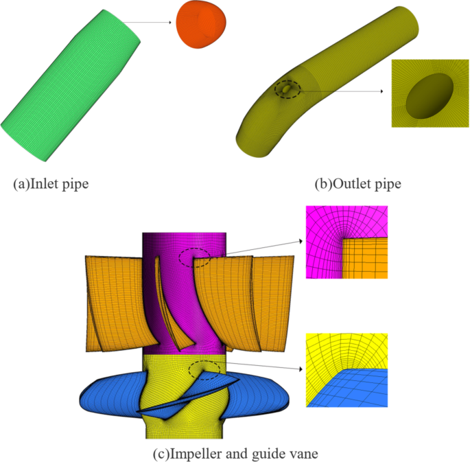
The impeller and guide vane are structured meshed within the turbo-grid to meet the quality standards. The inlet pipe featuring the water guide cone and the outlet pipe with the motor shaft are structured in ICEM CFD, and the mesh quality is over 0.4, which indicates good quality. Figure 2 below showcases the grid design of the impeller, guide vane, inlet pipe, and outlet pipe.

Grid model of each component of the axial-flow pump.
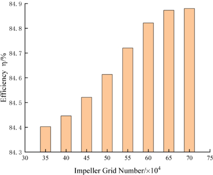
Verification of grid independence aims to minimize or eliminate the impact of the quantity and size of grids on the computation results. As the impeller is a rotating component while other elements are stationary, it is crucial to validate the quantity of the impeller grids to ensure accuracy in the calculations. Under the designated operating conditions, eight distinct impeller grid quantity schemes were implemented to assess impeller grid independence. Figure 3 illustrates that as the quantity of impeller grids increases from 651,152 to 710,444, the change in pump efficiency slows considerably, and the efficiency values’ growth rate is below 2%. Therefore, the total number of impeller grids is approximately 651,152, and the grid count for the entire axial-flow pump is roughly 4.5 million.

Verification analysis of impeller grid independence.
The quality of the grid significantly affects the outcomes of numerical simulations. It is essential to ensure grid convergence to achieve a balance between computational resources and the accuracy of numerical calculations. The GCI (Grid Convergence Index) criterion from the Richardson extrapolation method is utilized to confirm the mesh convergence. Ultimately, three groups of fine mesh N1 = 4,511,756, medium mesh N2 = 1,316,776, and coarse mesh N3 = 573,075 are engaged to analyze the mesh convergence of the pump. The grid refinement coefficients are all greater than 1.3. Subsequently, the performance parameters of the pump are evaluated through discretization error analysis. Refer to the GCI calculation program.of Yang et al.32. Table 2 presents the computational results. The convergence index GCI21 is 0.154%, indicating a minor discretization error. Consequently, the final grid count is 4,511,756.
Numerical configurations
The discretization of the governing equations employs a finite element technique based on finite volumes, while the convective terms are executed in a high-resolution manner. The flow field resolution utilizes a fully implicit multi-grid combined resolution method, integrating the continuity and momentum equations. Table 3 below outlines the boundary conditions applied to the computational domain of the pump. The maximum number of iterations is configured to 2000 within the solver settings.
Design of various axial-flow pump impeller configurations
To evaluate the influence of different cascade densities on the axial-flow pump, based on the selected airfoil, the angle of airfoil placement, the maximum airfoil camber ratio, and the maximum airfoil thickness ratio are held constant. By adjusting the tip cascade density, the effect of varying cascade density on the performance of the axial-flow pump is investigated.
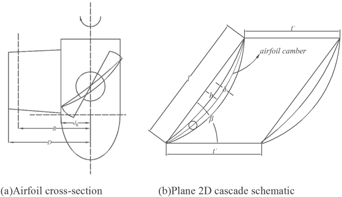
In the impeller’s design, the impeller blades are segmented into eleven airfoil sections. R represents the distance from each airfoil section to the center of rotation of the impeller. Figure 4a illustrates the cross-sectional schematic of the impeller airfoil. According to equations (30) and (31), when each airfoil section R is defined, the cascade distances t’ and r(i) remain constant. Figure 4b presents a schematic diagram of the two-dimensional blade channel.
$${t^{{prime }}}=frac{{2pi R}}{Z}$$
(30)
$${r_{left( {textual content{i}} proper)}}=frac{{{R_{left( {textual content{i}} proper)}}}}{D}$$
(31)
where i = 1, 2, 3…11, where 1 is the shroud, and 11 is the hub.

Cross-section of axial-flow pump airfoil and 2D cascade schematic diagram.
The cascade density of the airfoil section situated between the impeller hub and the shroud follows the law of equal energy, therefore the cascade density of each airfoil section can be managed through the two parameters σ1 and Zm, specifically based on the following equations: (32), (33), (34), and (35). To investigate the effect of σ1 on the performance of the axial-flow pump, Zm=1.433 is held constant. By modifying σ1, the influence of different cascade densities on the pump’s efficiency is analyzed.
$${lambda _{textual content{2}}}=frac{{{d_{textual content{h}}} cdot left( {{Z_{textual content{m}}} – 1} proper) cdot {sigma _{textual content{1}}}}}{{1 – {d_{textual content{h}}}}}$$
(32)
$${lambda _{textual content{1}}}={sigma _{textual content{1}}} – lambda {}_{{textual content{2}}}$$
(33)
$${sigma _{left( {textual content{i}} proper)}}={lambda _{textual content{1}}}+frac{{{lambda _{textual content{2}}}}}{{{r_{left( {textual content{i}} proper)}}}}$$
(34)
$${Z_{textual content{m}}}=frac{{{sigma _{{textual content{11}}}}}}{{{sigma _{textual content{1}}}}}$$
(35)
Where Zm denotes the number of cascade densities, σ1 is the cascade density at the shroud, σ11 is the cascade density at the hub, σ(i) is the cascade density of each airfoil section of the blade, and dh refers to the hub ratio.
The values for σ1 are 0.7, 0.75, 0.8, 0.85, 0.9, 0.95, and 1.0, amounting to a total of seven configurations, among which σ1 = 1.0, Zm=1.433 serves as the base configuration (OS) during the analysis; Table 4 illustrates the cascade density for the various configurations. Table 5 displays the sectional information of each airfoil under different configurations.

