

Technical Article
Grounding transformers is a deceptively simple task that carries significant implications for system safety and NEC compliance. This article explores the foundational concepts, common pitfalls, and practical techniques for properly grounding transformers in accordance with Article 250 of the National Electrical Code (NEC).
Understanding Grounding vs. Bonding
Firstly, it is important to understand the definitions of grounding and bonding, and their differences. Grounding involves connecting to a ground or a conductive body which extends to a ground connection. NEC Article 100 defines this as “connecting to earth or to some conducting body that serves in place of the earth.” This ground connection will typically lead to a grounding electrode conductor and a grounding electrode. Bonding is connecting to different points to establish electrical continuity and conductivity. It is defined by Article 100 as “connecting to establish electrical continuity and conductivity.”
So, what is the difference? Well, you can bond two electrical terminals together to establish continuity, but if neither terminal has continuity to ground (or a terminal that does), they are not grounded. Grounding would involve taking either terminal and bonding it to a grounded connection. So, any time you are grounding a system, you are bonding it with the ground. Conversely, if you are bonding two systems, it doesn’t necessarily result in a grounded system being formed.
Separately Derived Systems and Galvanic Isolation
This is important to understand, because transformers will, in most cases, require a bonded connection to ground to be considered properly grounded per NEC Article 250. To understand why this is, we first need to understand separately derived systems and galvanic isolation. An isolation transformer uses magnetic inductance to distribute electricity through two separate windings. This is known as galvanic isolation. You can think of an isolation transformer like a port between two cities. The port distributes goods (electricity) between the two cities (windings) utilizing the water between them (its core), but the two cities will always remain isolated. Therefore, the secondary of a transformer will be a separate electrical system that is isolated from the primary.
So, we know that the secondary of a transformer is a separately derived system. The NEC defines a separately derived system in Article 100 as: “An electrical source, other than a service, having no direct connections to circuit conductors of any other electrical source other than those established by grounding and bonding connections.” A transformer has no inherent ground connections. When forming a new system, unless the transformer is bonded to ground, the secondary system will remain ungrounded, and you may get floating voltages due to capacitive coupling to ground. The secondary winding does not have a solid connection until formed.
Proper Grounding Procedures
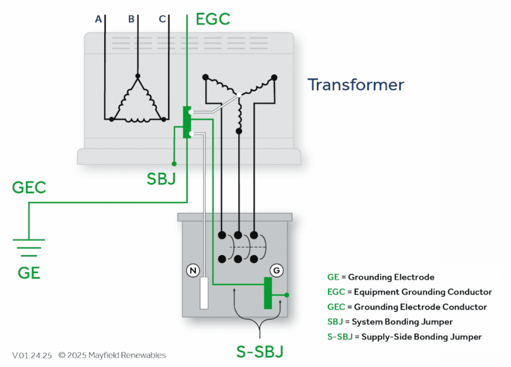
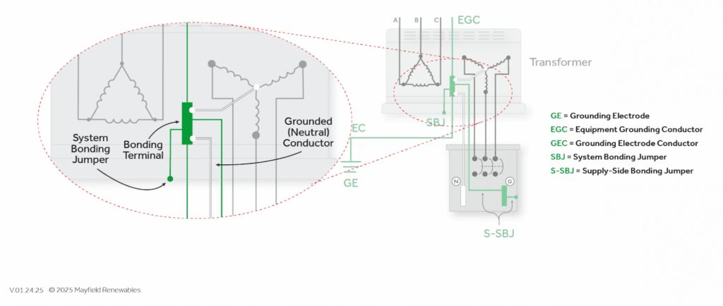
Forming a ground connection with a transformer is easy. This ground connection must be made using a system bonding jumper and formed at or before the first disconnecting means of the system. The system bonding jumper must be sized based on the largest ungrounded conductor of the derived system in accordance with NEC Table 250.102(C)(1). For example, a 250 kcmil phase conductor would require a minimum 2 AWG copper system bonding jumper. Typically, this ground connection requirement is met by grounding at the transformer. Transformers will have equipment grounding terminals for this purpose. The neutral terminal of the secondary winding can be bonded to the equipment grounding terminal. The equipment grounding terminal should have a grounding electrode conductor connected to a separate grounding electrode from the service side.
Avoiding Parallel Ground Paths
It should be noted that whether you decide to ground at the panel or the transformer, it is imperative to make sure that this is the only place where the neutral and ground are physically bonded. One of the main points from NEC Article 250 is that parallel pathways to ground must not be formed. That way, when a ground fault occurs, there is only one low impedance pathway to ground. If a parallel pathway exists, there is potential for a fault current to circulate through the system.
Special Considerations for Transformer Vectors and Autotransformers
Transformer windings can affect grounding configuration and cause confusion, especially within the renewables sector. Transformer configurations that are common in the PV industry are rare in other industries. One such example is a wye-wye configuration, which is among the most common for PV distribution transformers. Wye-wye transformers have a primary neutral, which can become a headache for installers.
NEC 250.6(A) addresses this issue directly, stating that: “grounding and bonding shall be installed to prevent objectionable current from flowing on non-current-carrying metal parts of electrical systems, conductors, and equipment.” Grounding beyond the service neutral and the lack of a phase shift causes neutral current to flow on metallic paths and may allow primary-side harmonics to couple directly into the secondary winding. This means that the primary wye neutral termination should not be bonded to ground unless explicitly required by system design and permitted by code.
This would also apply to autotransformers, as they are not galvanically isolated systems, and therefore their neutral terminals should not be bonded to ground. Per NEC 450.3, autotransformers do not provide galvanic isolation and therefore do not qualify as separately derived systems. Grounding the secondary neutral may inadvertently create parallel paths. This is why it is always important to pay attention to the transformer topology.
Proper transformer grounding is more than a checkbox—it’s a safeguard against fault currents, system instability, and inspection failures. By understanding the principles of galvanic isolation, separately derived systems, and NEC Article 250, installers and engineers can ensure safe, compliant, and reliable installations.
Mayfield Renewables provides design and engineering services for solar-plus-storage systems, and feasibility studies for microgrid systems. Contact us today for a consultation.