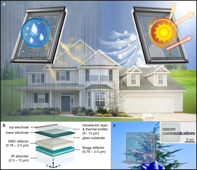
Design of TENG half in TeRC
To grasp the precept by which TeRC generates electrical energy via raindrops, it’s important to research cost provider, the predominant mechanism of liquid–strong contact electrification (i.e., triboelectrification). In line with the hybrid electrical double layer (EDL) mannequin26,33,34, throughout which the primary droplet collides with an electrically pristine strong floor, the interatomic potential barrier decreases because of the overlap of the electron cloud when the interatomic distance is inside the repulsive area, leading to electron switch (Supplementary Fig. 1). The transferred electrons and the chemically absorbed ions on the strong floor kind an electrostatic subject, ensuing within the formation of an electrostatically induced reverse cost of equal magnitude on the decrease electrode. When the following droplet collides with an collected negatively charged strong floor, the positively charged ions contained inside the droplet are interested in the strong floor because of the electrostatic induction impact, forming an EDL on the liquid–strong interface (Fig. 2a).
a Schematic of the hybrid electrical double layer (EDL) mannequin for explaining the liquid–strong triboelectrification. The measured (b) contact angle, (c) scanning electron microscope (SEM), and (d) atomic power microscope (AFM) photographs of the fluorinated-ethylene-propylene (FEP) movie. e Schematic of the electrical energy technology course of in the course of the droplet move sequence and (f) snapshots corresponding to every stage. g Experimental setup for investigating TENG efficiency of TeRC. h Self-cleaning and antifouling outcomes between TeRC and the glass pattern.
A triboelectric layer, an electret materials with excessive cost storage functionality, figuring out TeRC performances should possess a excessive hydrophobicity which promotes simple droplet sliding, leaving minimal residual droplets. To establish the optimum layer, numerous clear polymer movies are in contrast primarily based on contact angle and floor roughness. The contact angle measurement reveals that fluorinated ethylene propylene (FEP) reveals the best contact angle of 111.8° (Fig. 2b and Supplementary Fig. 2), which means that FEP movie is essentially the most hydrophobic, enabling droplets to roll off its floor effortlessly. Moreover, floor roughness for every movie is evaluated utilizing scanning electron microscopy (SEM) (Fig. 2c and Supplementary Fig. 3) and atomic power microscopy (AFM) (Fig. second and Supplementary Fig. 3). The outcomes definitively show that FEP movie has essentially the most substantial floor roughness among the many measured movies, which suggests that elevated roughness performs a vital function in enhancing floor hydrophobicity, considerably enhancing triboelectrification. Due to this fact, all through this examine, we undertake FEP movie because the triboelectric layer.
To research the conduct of electrons between TeRC and droplets, we characterize schematics of the droplet sequence flowing on TeRC (Fig. 2e) and captured corresponding snapshots (Fig. 2f). The proposed TeRC adopts a two-electrode configuration to extract electrical vitality by combining electrostatic induction and triboelectrification, remodeling interfacial to bulk impact to keep away from interfacial screening impact, whereas additionally decreasing structural complexity26; a thread-like conductive tape is hooked up as a high electrode, whereas the decrease electrode consists of an indium tin oxide (ITO) layer sputtered on a glass substrate. The 2 electrodes are straight related to the load resistance ({R}_{{{{rm{L}}}}}), forming a closed-loop system with the droplet. After the droplet collides with the FEP floor, the triboelectricity technology is categorized into 5 levels primarily based on the droplet motion: (i) When the droplet contacts with an electron-accumulated FEP floor, the cations within the droplet bind with the electrons on the FEP floor, forming a pseudo capacitor ({C}_{{{{rm{F}}}}}) on the contact interface. (ii) Whereas the droplet flows alongside the floor, cost switch to the exterior circuit doesn’t happen till it contacts the highest electrode, sustaining a switch-off state. (iii) When the droplet contacts the highest electrode, new pseudo capacitors are shaped between the triboelectric layer and droplet ({C}_{{{{rm{E}}}}1}), in addition to between the highest electrode and droplet ({C}_{{{{rm{E}}}}2}). Consequently, a closed-loop is established with the droplet resistance ({R}_{{{{rm{D}}}}}), transitioning to a switch-on state. Then, electrons beforehand saved in ({C}_{{{{rm{F}}}}}) quickly move to the decrease electrode (Supplementary Fig. 4). (iv) Throughout droplet shrinkage, electrons return to the highest electrode, and ({C}_{{{{rm{F}}}}}) is recharged by ({C}_{{{{rm{E}}}}1}) and ({C}_{{{{rm{E}}}}2}). The spreading and shrinking of droplets characterize the charging and discharging phenomena of the pseudo capacitors. (v) Because the droplet continues to move away from the highest electrode, the electrical energy technology cycle ends. To measure triboelectric efficiency of TeRC, we configure the experimental setup to launch droplets on the drop top ({h}_{{{{rm{drop}}}}}) and the drop angle ({theta }_{{{{rm{drop}}}}}) (Fig. 2g).
Moreover, TeRC has a self-cleaning and antifouling potential from out of doors contamination owing to robust hydrophobic floor, which successfully prevents the discount in triboelectric efficiency (Fig. 2h). To evaluate this, chalk powders are employed as mud, and the inked water to facilitate simple identification of residue on the floor. When water is dropped on the standard glass, it tends to remain, hindering efficient cleansing within the presence of mud and leaving residue on the floor. In distinction, when water is dropped on TeRC, droplets simply roll off, carrying away the powder, on this case, TeRC could be effortlessly cleaned with droplets.
TENG efficiency of TeRC
All through this work, we preserve ({R}_{{{{rm{L}}}}}), movie thickness (d), ({h}_{{{{rm{drop}}}}}), ({theta }_{{{{rm{drop}}}}}), frequency, droplet quantity, and water sort mounted at 10 MΩ, 250 μm, 45 cm, 45°, 2.5 Hz, 40 μL, and faucet water, respectively, to discover the affect of every parameter. On this configuration, we measure {the electrical} sign of a single droplet in open-circuit situations (Fig. 3a). When the droplet touches the highest electrode, an instantaneous pulse-like electrical sign is measured, reaching as much as 415.43 V, and electrons are launched from ({C}_{{{{rm{F}}}}}). After discharging, a notable remark reveals the detection of a adverse sign with the shrinking of droplet, indicating the backflow of electrons attributed to the recharged ({C}_{{{{rm{F}}}}}) by ({C}_{{{{rm{E}}}}1}) and ({C}_{{{{rm{E}}}}2}). To calculate the output energy, we sweep ({R}_{{{{rm{L}}}}}) (0.1–10 MΩ), to extract voltage indicators (Fig. 3b). By dividing the output energy by the utmost spreading space of the droplet ({S}_{{{{rm{drop}}}}}), we calculate the ability density, reaching a most worth of 248.28 W m−2 at 0.5 MΩ. Furthermore, the switch cost (q) additionally reaches the utmost worth of 30.53 nC on the similar ({R}_{{{{rm{L}}}}}) (Fig. 3a and Supplementary Fig. 5). Moreover, TeRC produces 2.95 μJ of vitality from a single droplet at similar ({R}_{{{{rm{L}}}}}), serving as an indicator for evaluating harvested vitality (Supplementary Fig. 6).
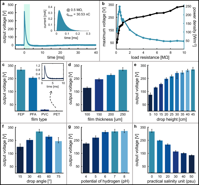
a Output voltage sign extracted from a single droplet within the open-circuit situation. The inset shows the present and corresponding switch cost on the optimum load resistance. b Peak voltage as a perform of load resistance and the corresponding energy density. c Peak voltage in response to movie sort. The inset portrays the voltage sign for the polyethylene terephthalate (PET) movie. Comparability of peak voltage in response to the (d) movie thickness, (e) drop top, (f) drop angle, (g) droplet potential of hydrogen (pH), and (h) droplet sensible salinity unit (psu). All error bars characterize the utmost and minimal, respectively.
The collection of the triboelectric layer is an important consider figuring out the triboelectric efficiency. The voltages are extracted utilizing numerous polymer movies beforehand employed for the comparability of hydrophobicity (Fig. 3c). The height voltage of the droplet over 10 s is highest for FEP of 317.57 V, whereas the output voltage from different movies aligned with the hydrophobic tendency. Notably, {the electrical} sign utilizing polyethylene terephthalate (PET) will not be detected after the primary droplet, as a result of the extended shrinkage time of the droplet results in the merging of subsequent droplets, ensuing within the electrical cancellation impact (Supplementary Fig. 7). Consequently, we confirm that larger hydrophobicity generates a extra secure and better triboelectric efficiency (Supplementary Fig. 8).
If we assumed that FEP movie is way thicker than EDL, the voltage loaded ({C}_{{{{rm{F}}}}}) could be simplified35,36:
$$V=frac{{qd}}{{epsilon }_{{{{rm{FEP}}}}}{S}_{{{{rm{drop}}}}}}$$
(1)
the place ({epsilon }_{{{{rm{FEP}}}}}) characterize the permittivity of FEP movie. The output voltage is proportional to (d), and we experimentally affirm that the output voltage will increase with (d) of FEP movie (Fig. 3d). Furthermore, when it comes to RC a part of TeRC, a thicker FEP movie features as a thermal emitter with larger absorption functionality within the infrared (IR) vary (Supplementary Fig. 19).
As well as, we analyze the output voltage in response to ({h}_{{{{rm{drop}}}}}), observing a rise in output voltage with ({h}_{{{{rm{drop}}}}}) (Fig. 3e). As ({h}_{{{{rm{drop}}}}}) will increase, the rate the place the droplet impacts the FEP movie additionally will increase. Then, with the rising Weber quantity, extra electrons take part in triboelectrification26,37. Notably, the droplet inherently carries gravitational potential vitality, and the vitality conversion ratio (eta) is an important issue to judge the renewable vitality supply. By evaluating {the electrical} vitality derived from the output energy, (eta) information a constant worth about 2.5% no matter ({h}_{{{{rm{drop}}}}}), which confirms that potential vitality is stably transformed into electrical vitality (Supplementary Fig. 9).
Triboelectric efficiency additionally is dependent upon ({theta }_{{{{rm{drop}}}}}). The height voltage will increase with ({theta }_{{{{rm{drop}}}}}), reaching its peak at 45°, and reduces as ({theta }_{{{{rm{drop}}}}}) turns into bigger, as a result of the contact electrification is carefully related to ({S}_{{{{rm{drop}}}}}) and the electrical energy discharging time38,39 (Fig. 3f). As ({theta }_{{{{rm{drop}}}}}) will increase, because of the droplet skimming the floor, ({S}_{{{{rm{drop}}}}}) decreases, resulting in a discount within the involvement of electrons in electrification. Then again, because the discharging time decreases, the time out there for the electrification response diminishes (Supplementary Fig. 10). Thus, these two variables synthetically affect the triboelectric efficiency.
TeRC could be utilized to numerous conditions past raindrops, equivalent to ocean environments. Nevertheless, earlier research have reported a discount in triboelectric efficiency owing to seawater, however the investigation into the underlying causes has been inadequate40,41. To evaluate this potential, we consider the triboelectric efficiency primarily based on the potential of hydrogen (pH) of droplets (Fig. 3g). We observe an rising pattern within the output voltage because the pH shifted from acidic to alkaline. This can be attributed to the upper focus of hydron with reducing pH, inducing a screening impact that hinders electrostatic induction42,43. Nevertheless, contemplating that the pH of worldwide seawater is ~8.1, it may be inferred that the poor triboelectric efficiency of seawater will not be primarily influenced by pH. Due to this fact, we examine electrical indicators by adjusting salinity utilizing sodium-chloride (NaCl), and noticed that as the sensible salinity unit (psu) will increase, the triboelectric efficiency deteriorates (Fig. 3h). It is because dissolved NaCl dissociates into Na+ and Cl−, and as psu will increase, the ion focus rises. The extreme free ions within the droplet, attributable to the excessive ion focus, induced a screening impact. Moreover, we consider the potential of TeRC system in actual environments by verifying its triboelectric efficiency utilizing rain water, and confirmed its potential to take care of wonderful electrical energy technology capabilities (Supplementary Fig. 11).
Design of RC half in TeRC
To chill down an enclosed area underneath direct daylight whereas sustaining seen transparency, the next optical properties must be met; (i) Excessive reflectivity in ultraviolet (UV) and near-infrared (NIR) areas, (ii) excessive transmittance within the seen area, (iii) excessive emissivity within the AW, and (iv) excessive thermal radiation absorption of the interior enclosed system (Fig. 4a). To this finish, RC consists a photo voltaic reflector with excessive AW emissivity materials and thick polydimethylsiloxane (PDMS) layer. The reflector consists of two elements; the dielectric-metal-dielectric (DMD) layer, a skinny metallic movie sandwiched between dielectric layers, and the underside Bragg mirror (Fig. 4b). The permittivity of the dielectric used within the DMD layer is way higher than that of the metallic, proscribing the floor plasmon coupling and decreasing absorption, making it clear in desired frequencies and strongly reflecting NIR mild44,45. Right here, we’ve got chosen titanium dioxide (TiO2) and silver (Ag) for top permittivity distinction. To additional enhance NIR reflection, we devise an extra Bragg mirror layer on the backside with alternating silicon dioxide (SiO2) and TiO2 layers. Preserving the thickness of the Ag layer mounted to 24 nm, the remainder of the thickness profile of the multilayer construction is optimized to have excessive transparency within the seen and excessive reflection in UV and NIR utilizing the particle-swarm-optimization algorithm (Supplementary Figs. 14 and 15). Lastly, the PDMS layer is positioned on the backside which is answerable for the IR radiation absorption of the system beneath it for efficient cooling of an overheated enclosed area46.
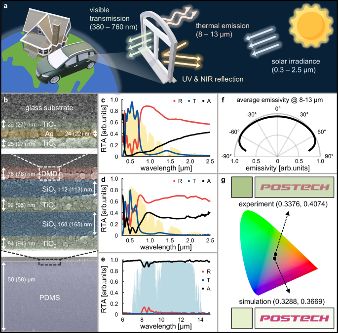
a Schematic of a really perfect clear RC which transmits seen mild, displays ultraviolet (UV) and near-infrared (NIR) mild, and emits thermal vitality by blackbody radiation within the atmospheric window (AW). b Scanning electron microscope (SEM) picture of the fabricated TeRC pattern. The overall construction consists of dielectric-metal-dielectric (DMD) reflector, Bragg mirror and IR absorber underneath the glass substrate. The values point out the optimized (fabricated) thickness profile of every layer. c Simulated and (d) measured reflectance, transmittance, and absorptance (RTA) spectra of the designed TeRC. e Measured IR RTA spectra of TeRC. f Common angular absorption of RC half in TeRC, which is calculated by taking common within the AW over a broad vary of incident angles. g The calculated transmitted picture via TeRC and the anticipated colours utilizing simulated and experimentally measured transmittance spectra and their CIE 1931 xyY shade area.
The optimized TeRC exhibits a excessive seen transparency most of 95.7% and an NIR photo voltaic reflectance most of 88.3% (Fig. 4c). The fabricated TeRC reveals barely diminished seen transparency most of 80.0%, and NIR photo voltaic reflectance most of 70.9%, and total larger absorptance than the optimized construction (Fig. 4d). This discrepancy is attributed to inherent losses within the precise supplies together with TiO2, Ag, and ITO (Supplementary Fig. 16). Notably, contemplating that the TENG-only half in TeRC registers a measured seen transmittance beneath 84.7% (Supplementary Fig. 17), it’s anticipated that the fabricated pattern aligns with or falls beneath this threshold. Nevertheless, regardless of the noticed discrepancy, the fabricated TeRC maintains commendable degree of seen transmittance, enabling clear visibility (Fig. 1c).
Moreover, the measured emissivity covers the entire AW indicating efficient thermal radiation to outer area (Fig. 4e). The angular emissivity of TeRC exhibits omnidirectional radiation (Fig. 4f). The anticipated colours and transmitted photographs are visualized primarily based on the simulated and measured spectra (Fig. 4g and Supplementary Fig. 18). The colour coordinates are (0.3288, 0.3669) for the simulated and (0.3376, 0.4074) for the measured TeRC, displaying a greenish shade.
RC efficiency of TeRC
To characterize the cooling potential of TeRC, the cooling energy is calculated primarily based on their optical spectrum (Supplementary Word 22). To contemplate TeRC as an alternative choice to standard glasses, we consider radiative cooling potential by assuming the construction is positioned on an absorbing chamber, mimicking clear glazing of automobiles or buildings the place a lot of the non-reflected mild is absorbed inside. We examine the optical and cooling properties of TeRC with TENG-only pattern and a standard naked glass. The radiated energy from the pattern ({P}_{{{{rm{rad}}}}}), energy absorption from the incident atmospheric emission ({P}_{{{{rm{atm}}}}}), and the incident photo voltaic flux absorbed by the pattern ({P}_{{{{rm{solar}}}}}) are simulated underneath ambient temperature ({T}_{{{{rm{amb}}}}}=303) Okay (Fig. 5a). For the reason that non-reflected mild is all absorbed contained in the chamber, we set the emissivity (varepsilon=1-R) the place (R) represents reflectance. There isn’t a important distinction for ({P}_{{{{rm{rad}}}}}) and ({P}_{{{{rm{atm}}}}}) due to the similar pattern temperature and successfully excessive AW emissivity for all three buildings (Supplementary Fig. 19). Essentially the most notable distinction comes from ({P}_{{{{rm{solar}}}}}). The NIR reflecting layers of TeRC contribute to decreased ({P}_{{{{rm{solar}}}}}) of 411.54 Wm−2, which is considerably decrease than that of TENG-only, and the glass samples that are 710.8 W m−2 and 827.54 W m−2, respectively. Consequently, TeRC exhibits the best cooling energy than the 2 references at numerous temperatures. (Fig. 5b). Equilibrium temperatures the place the cooling energy is zero at numerous non-radiative warmth switch coefficient ({h}_{{{{rm{cc}}}}}) are additionally calculated (Fig. 5c). Because of the distinction in photo voltaic absorption, the equilibrium temperatures of TeRC are decrease than these of TENG-only and the glass samples by greater than 20 and 40 °C, respectively.
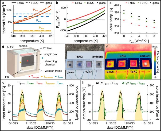
a Numerically calculated thermal fluxes and equilibrium temperatures for the ambient temperature of 303 Okay. Thermal flux phrases comparability of the proposed raindrop triboelectric nanogenerator and radiative cooler (TeRC), triboelectric nanogenerator (TENG)-only pattern, and glass. b Pcool of TeRC, TENG, and glass. c Equilibrium temperatures for various efficient conduction and convection warmth switch coefficient hcc. Rooftop measurement carried out at Seoul, Republic of Korea from 10/10/23 to 13/10/23. d Schematic and (e) {photograph} of the rooftop measurement setup. f {Photograph} captured utilizing an infrared (IR) digicam for measuring atmospheric window (AW) flux. g Temperature variation in the course of the rooftop measurement. Yellow shaded space represents the measured photo voltaic irradiance. Tglass, TTeRC, and TTENG represents interior temperature of the absorbing chamber on which the reference and the cooler pattern are positioned, respectively. Tchamber denotes the temperature exterior the absorbing chamber however contained in the acrylic field and Tamb is the temperature exterior the acrylic packing containers. h Temperature variations, ∆T1 = Tglass − TTeRC and ∆T2 = TTENG − TTeRC.
To show the cooling impact of TeRC, we conduct an out of doors measurement with a chamber setup resembling a superbly absorbing interior system (Fig. 5d and Supplementary Fig. 21). To check the cooling impact of TeRC to glass and TENG, two reference packing containers and an ambient field with out the testing pattern are measured concurrently (Fig. 5e). The quantity of AW flux emitted by 4 comparisons are visualized as thermal-IR photographs (Fig. 5f). The temperature variations are measured over 3 days on the 4 factors; interior temperature of the absorbing chamber in TeRC field ({T}_{{{{rm{TeRC}}}}}) and within the two reference packing containers ({T}_{{{{rm{glass}}}}}) and ({T}_{{{{rm{TENG}}}}}), the temperature exterior the absorbing chamber within the ambient field ({T}_{{{{rm{chamber}}}}}), and ambient temperature exterior the acrylic packing containers ({T}_{{{{rm{amb}}}}}) (Fig. 5g). Notably, ({T}_{{{{rm{TeRC}}}}} , < , {T}_{{{{rm{TENG}}}}} , < , {T}_{{{{rm{glass}}}}}) exhibits the TeRC can settle down interior temperature of an enclosed area underneath direct daylight by reflecting undesired vitality within the non-visible photo voltaic spectrum vary. ({T}_{{{{rm{TeRC}}}}} , < , {T}_{{{{rm{glass}}}}}) additionally attributed to robust photo voltaic reflection and the massive overlaying space of TeRC pattern. The temperature distinction between samples is considerably excessive in the course of the daytime. Particularly, (Delta {T}_{1}={T}_{{{{rm{glass}}}}}-{T}_{{{{rm{TeRC}}}}}) reaches most 24.1 °C and common of 8.2 °C, whereas (Delta {T}_{2}={T}_{{{{rm{TENG}}}}}-{T}_{{{{rm{TeRC}}}}}) reaches most 18.0 °C and common 5.7 °C (Fig. 5h).
Potential software of TeRC
The triboelectricity generated via TeRC could be utilized to versatile low-power gadgets. First, we cost capacitors utilizing a rectifier diode circuit (Fig. 6a). By charging the capacitor, a secure electrical provide is achieved, and we efficiently cost a 1 μF capacitor to 2 V in ~50 s (Fig. 6b). Furthermore, we show the potential of TeRC by powering 100 light-emitting diodes (LEDs) utilizing raindrop vitality (Fig. 6c, Supplementary Fig. 22, and Supplementary Film 1). Moreover, to show the potential real-world applicability of TeRC, we organize a number of TeRCs in an array and measure their electrical energy technology, proving that the TeRC array produces electrical vitality at a a lot larger frequency than a single TeRC (Supplementary Fig. 23). As well as, we consider the geographical dependency of TeRC utilizing world long-term-mean precipitation in July47 (Fig. 6d). The precipitation is predominantly concentrated close to the equator, identified for dense tropical rainforests. In these areas, TeRC could be utilized for supplying energy to harsh environments.
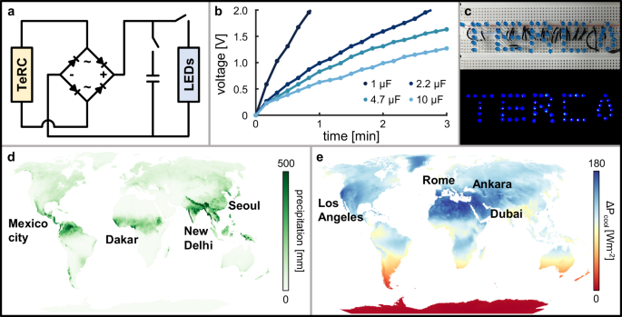
a Circuit diagram with a rectifier diode to make the most of {the electrical} vitality from TeRC. b Charging voltage on capacitors charged by TeRC. c Image of light-emitting diodes (LEDs) powered utilizing TeRC. World maps indicating potential areas for the functions of (d) triboelectric nanogenerator (TENG) and (e) radiative cooler (RC) half in TeRC, primarily based on world local weather knowledge.
Subsequently, the worldwide radiative cooling energy is estimated. The cooling energy extremely is dependent upon the pattern temperature and the incident photo voltaic irradiation, that means native climate situations can considerably have an effect on TeRC efficiency. To judge the cooling impact in comparison with the pristine glass, the cooling flux distinction (Delta {P}_{{{{rm{cool}}}}}={P}_{{{{rm{TeRC}}}}}-{P}_{{{{rm{glass}}}}}) is calculated primarily based on the Earth ambient air temperature and photo voltaic irradiance in July48. The pattern temperature is about equal to the Earth ambient air temperature (Supplementary Fig. 24). The calculated map portrays robust geographical dependency resulting from regional local weather variations (Fig. 6e). Areas with excessive solar energy are likely to have larger variations owing to robust reflecting properties of TeRC within the non-visible photo voltaic vary. (Delta {P}_{{{{rm{cool}}}}}) exhibits an analogous distribution sample with the photo voltaic irradiance map, that means that it has larger potential in areas underneath robust daylight (Supplementary Fig. 25). Consequently, we’ve got confirmed that TeRC, with its performance as each TENG and RC, can carry out multifunctionality in the identical area in response to local weather situations. Moreover, we’ve got recognized its potential to be extra appropriately utilized, contemplating geographical situations.

